KMZ Horizont Camera Servicing
The Horizont Panoramic Camera
Horizont, made by KMZ factory in former Soviet Union from year 1967 to 1973, is a very interesting panoramic camera. It's designed around a swivel lens that draws the photo on a curved film plane. The dimension of the negative is 24×58 mm which allows 21 panoramic exposures on a normal 135 film for 36 exposures. The lens has a focal length of 28 mm and a settable aperture from F/2.8 to F/16. There is no focus control.
 |
| The OF-28p lens produces sharp and contrasting photos. |
 |
| Panoramic photos taken with swivel lens cameras have a distinctive character. |
Unlike the predecessor FT-2, the swivel speed of the lens is constant. Exposure time is set with the help of a variable width of the slit. If completely opened, the exposure speed corresponds to 1/30 s while other settings are 1/60, 1/125 and - on majority of cameras marked just with a dot - 1/250 s.
The Horizont is equipped with a detachable viewfinder that is both bright and large. It even employs a bubble leveler visible from the top and through the viewfinder. Due to the very large field of view (120 degrees), the removable handle comes in handy for holding the camera so no fingers are visible on photos. The leather case has a neat feature that enables carrying the camera with the handle sticking out of it. There were also special filters available.
More about the camera and its variants can be found
on "soviet cams" website. Please note that the camera shown on the photo above has an unoriginal film speed memo dial on the top of the controls.
The Problems
Like the camera, some of it's problems are also specific. The most common ones are:
- Light leaks - bright vertical thick lines on the left or/and right side of the negative.
- Uneven turret rotation - vertical lines of uneven exposure over the entire negative.
- Slow turret rotation - often in combination with uneven rotation. I believe the turret should complete it's turn in approximately 250 - 300 ms.
- Broken bubble leveler
- Problems with film transport - shutter doesn't pop up after exposure and gears are skipping, or film may be trapped in the film chamber because it isn't wound on the spool as it should be.
I bought a camera with all of the above problems. Unintentionally, naturally. It still produced some photos that fascinated me. So I bought another one that should have been in a better shape. Luckily, it was. But having two Horizonts, I decided to take a risk and try to fix the first one. I found that all of the problems above are relatively easy to fix, except for the broken bubble leveler. Frankly I didn't try it because my viewfinder is missing a mirror that reflects the bubble leveler.
Additionally I noticed some horizontal lines on some photos. I suspect the reason was the uneven edge of the slit - I didn't try to fix that yet.
A great help during dismantling was
Pierre Kerr's website. But since the photo resolution on the mentioned website isn't very good, I decided to document my servicing expedition. I also have some additional comments that I hope will be valuable for some Horizont owners.
 |
| Massive light leaks. The one on the left arises when the shutter is cocked while the right one when it's released. The origin of the middle one is a bit less evident. In my opinion it emerged while cocking the shutter when the film is travelling inside the film chamber or it may be a second reflection of the first one. Horizontal banding is also clearly visible on this shot. |
 |
| Vertical banding. Light leaks are not as evident since I was more careful and strictly carried the camera in a bag to avoid light exposure. |
The Service
I will mainly guide you trough the dismantling process and at some steps there will be solutions for specific problems given as well. I have to write a short disclaimer at this point: I'm an enthusiast collector of vintage cameras that likes to use them and tries not to spend a lot of money for his hobby. I'm not educated in camera servicing and I have little experience. So if someone that reads this has any comment or suggestion about what I did (wrong) or I should do, please, write a comment.
The Tools I Used
- Screwdrivers set - nothing special is needed here.
- Decent tweezers.
- Pointed pliers.
- Spanner wrench - I own these but these look better since the tips can get closer together.
- Compasses - I replaced the graphite and needle with two nails. Just to compensate the spanners that are unusable with some screws on Horizont where the tips must be very close together.
- Wooden toothpicks - usable for applying grease and some other jobs where one should be careful not to leave scratches.
Additionally, a notebook and some adhesive tape may come in use during the procedure. If one wants to fight the light leaks, flexible foam, appropriate piece of fabric and multipurpose glue is needed. For lubrication of the gearing I used bearing grease. I believe (I read about) a silicon grease would be better, but the store where I went did't have it for sale.
First step: Eat some chocolates. The packaging is beyond useful.
The Real Deal
Let's start with removing the top. Naturally, the viewfinder should be detached first. The first bigger barrier are the strap lugs. Let's start here since the appropriate tool is needed to remove them and it's better to find out that if tool needs to be acquired at the beginning.
I protected the casing with some adhesive tape. One part of the strap lug is rotating freely, but note that the other part touching the casing stays fixed. There are 2 to 4 slots in that part that can match with two slots of the rotating part.
Align the two slots and stick the compasses (or the tool you will use) in them. To prevent bending the compasses I held them with the pliers close to the tips.
Unwind the strap lugs on both sides. There is also a screw on each side of the camera below the strap lugs. The third one - a bit bulkier - is located on the viewfinder holder (accessory shoe). Unwind all three.
There is a sheet metal plate on the accessory shoe. You can remove it to clean some dirt below or leave it there.

All the knobs on the top plate need to be removed. The shutter cocking/film advance knob is held in it's place with a screw with two holes. Unwind it and the knob should be easily removed.
Under the knob there is a ring screw which should be removed with the spanner wrench. Be careful since the spring will pop out the exposure counter when unscrewed.
There is a big washer under the spring.
Prior to removing the shutter speed and aperture dials, remember the settings. It isn't very critical since you can determine the speed setting from the gap width and set the aperture to fully open position later, but it's a good practice in camera servicing to remember the initial settings. There is another screw with two holes in the middle of the dials.
When unscrewed, the film speed memo dial can be lifted out. There are some washers underneath. I say "some" because you may think at first that there is one. Bot then it separates into two. And later into three... All the Horizont's thin washers multiply when you look away. Thus it's a smart thing to store them in a separate container.
The aperture and shutter speed dials can be lifted out of the cavity. One gear will probably stick to the dial while another will stay inside. However, both gears have notches to align with the dials. When assembling the camera back you should only be careful not to miss one gear tooth since offset of the settings indicator may be caused.
It should be clear to you what needs to be done with the rewind knob. Mine refused cooperation and a surprisingly large amount of force was needed to unscrew it.
Now the top plate can be removed. Just be careful a bit since it may get stuck at the film chamber doors hinge. Bend the metal slightly if necessary to get it pass.
And this is what you should see.
- Shutter release - you are able to press it.
- Shutter cocking knob - you can cock the shutter by turning it. It's a bit harder than with a mounted knob, but it's OK for basic testing before the camera is fully assembled.
- The shaft that prevents premature shutter knob return. If the shutter button is just briefly pressed and released before the drum completes it's travel, the spring would return the gear that is holding the drum from rotation and screw up the exposition if there was no mentioned shaft.
- Aperture and shutter speed setting gears.
- A metal insert that moves the shaft "3" to its initial position and allows the shutter knob to pop back up.
- Springs that produce clicks when setting the aperture or exposition.
Prior to unscrewing the three screws with the large heads around the shutter cocking part, I suggest you fire the shutter. Note how the gear is pushed down to let the turret move.
Leave the smaller screws intact. A spring will lift the whole assembly out.
In my case the "shaft no 3" was stuck. I sprayed some WD40 and it was free in a second. I think there's nothing wrong with changing the old grease on the gears with fresh one, despite the fact that friction of this part has nothing to do with banding problems. However, if you have any problems with the film winding spool (in my case it was too loose, it may cause problems if it's too stiff as well), you should take a closer look at this part.
There is a threaded shaft where a spring is squeezed with two nuts. The more the spring is squeezed, more friction is applied to the film winding spool.
Removing the bottom case is very easy. There are four screws that need to be unscrewed and the metal plate comes off easily.
Under "the hood" the most interesting part is the speed regulator. Try to move the turret with your finger to the opposite direction and release it. If your Horizont turret movement is too slow, this regulator may be a reason. The edge where the brass weights are sliding may be corroded or dirty. The other reason may be the gears under the speed regulator assembly.
- Turret speed regulator - the brass parts press to the walls of the metal ring. The faster the turret turns, the more they press. Thus the constant speed is reached.
- Turret bottom bearing.
- Turret stoppers - you don't have to remove them. However, they are easily calibrated if needed.
- Spring holder insert - here the spring can be wound or unwound.
- Film rewind button shaft - if the turret is in released position, this shaft holds the film rewind button pressed during film rewinding.
- Film rewind button.
In the central part there is a drum bearing and around is an insert with three screws. I suggest you mark where the top is (I marked it with an arrow) since this part holds the spring tension. Try to push it down while unscrewing the three screws since the tension will try to rotate it and the last screw thread may be damaged if all the force will be pushing it. On the other hand you don't want it to rotate freely after the last screw is removed. When the unscrewing is complete, slowly decrease your pressure and allow the part to rotate. Count the turns. I counted 2 and 3/4 with my Horizont.
The insert doesn't fall out freely. Some jiggling is needed, but nothing special.
Remove the three screws of the metal plate holding the speed regulator (on the image bellow the spring holding insert is still in it's place... Sorry for that). You don't have to remove the screws around the regulator. However, if your Horizont is turning the turret a bit slow or uneven, remove them and clean the surface where the brass parts are gliding. Add a very thin layer of grease there.
When assembling it, don't tighten the screws. Leave them loose so that the ring will freely move and pull the drum to one side and release it. The force on the brass weights will align the ring to the center. Tighten the screws now.
Remove the metal plate and be careful about the washers that may be underneath. Remember their position. There is no rule where they are as far as my knowledge goes. Remove the gears. I believe there is nothing wrong with adding a little grease to them when assembling back.
Back to the top part, remove the metal cast that holds the drum. There are three screws to remove (shown with the red arrows). The screw marked with the blue arrow on the picture below doesn't need to be removed. The screws that hold the shaft marked with the green arrow can also be removed after taking out the drum holder.
Prior to taking out the turret, there are two small metal shafts that should be carefully removed. I suggest that you mark their position before unscrewing the screws holding them. As seen on the photo above I scratched marks with the screwdriver. The one shown on a photo below allows the exposure slit to open when the shutter is cocked and the other - showed on the picture above - closes it for the time the shutter is being cocked (since the slit would otherwise be traveling over the film exposing it).
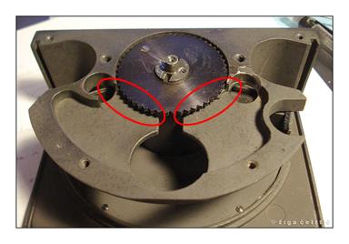
Now the turret can be carefully removed. Watch for the washers since they are positioned above and below the large cogwheel under the turret. And again, you should be careful about how many of them there are since they are multiplying like rabbits :)
And the reason for light leaks is revealed in all it's glory. Dirty felt on top of sticky non elastic old foam. This needs to be removed and replaced. I had luck finding a fabric that is very similar to the felt used originally. However, you can restore the original felt with removing the foam and gently cleaning it. The foam is useless and very hard to clean. I removed as much as I could (I tried with white spirit, alcohol and acetone without any significant breakthrough).
I had only thick foam so it was far from perfect since I had to literally carve the chunks out. I recently found a much better shaped foam, but for the proof of concept this was also OK. This is how the replacement looked outside the camera...
And in it's place. I used a multipurpose glue sold in tubes for hobby and even school use. Don't make the inserts too thick and too wide since they can interfere with the turret movement or tear when you will insert the turret back. Maybe you will have to make several of them before finding the best dimensions. Some patience is needed here. Since the foam flexibility may differ, I can't give you exact measurements. For the felt size use the original one as a sample.
When putting the turret back, the bottom cogwheel orientation is important. Refer to the picture below if you hadn't remembered it's position. Be careful on the film rewind button shaft at the bottom of the camera that may interfere with the turret when pushing it down.
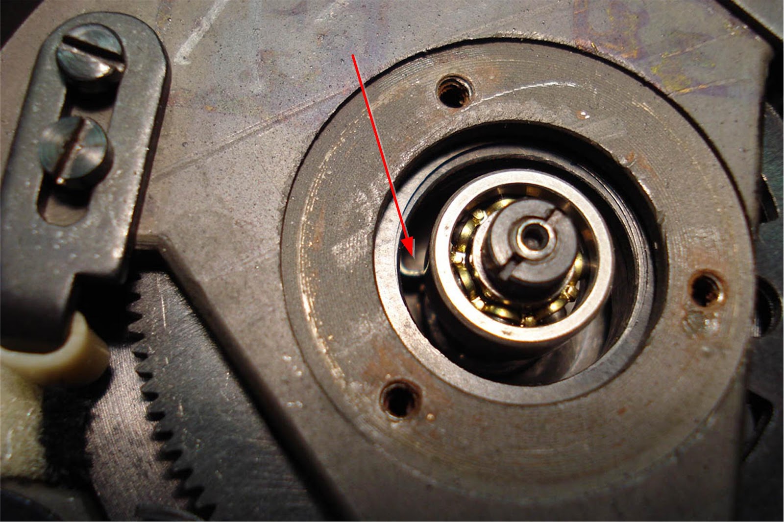
When inserting the spring holding insert, be careful with the slits cut in it since one has to align with the spring inside the drum (red arrow). Once inserted, wind the spring. Don't mess the winding direction since you can damage the spring. Put in the screws but be careful not to damage the threads. Hold the insert in it's place and align it with the holes perfectly. Don't tighten the screws too much.
Be careful with other screws as well. While putting the camera back together, test it's functionality. You can see if the drum is turning at the right speed without shutter cocking mechanism in place. If it turns uneven or too slow, check the speed regulator and the cogwheels. It's not hard to locate the source of the problem.
Check that the slit is open during exposure and closed during rewinding.
It may easily happen that the shutter doesn't return to its position when the camera is assembled. It happens because the gears of the shutter cocking mechanism aren't aligned with the turret cogwheel. There is some tolerance in shutter cocking mechanism assembly. Partially unscrew it and align it so the operation is flawless. It can also be tested before the top is put on the camera. I suggest you also insert a used film inside the camera (i suppose you have one) and test how it rewinds.
If the problems emerged when the top was put back in place, check the settings part. You may have turned the gears around or tighten the screw too much. Maybe the metal plate was bent while pushed back on top.
Finally, when this camera is working nicely, you are rewarded with some unique photos.